Innovative designs and off-shore construction methods had to be implemented in order for this unique multi-span cable-stay bridge to become a reality. Note the shallow foundations on reinforced soil, the continuous and fully suspended deck for the full length of the bridge (2.252 m), the huge dissipation system, the stay cables equipped with special para-seismic devices, the expansion joints which can accommodate large displacements in all directions.
The design and construction was led by the French company Vinci together with the largest Greek construction companies (Aktor, J&P and Athena).
Environment
 The environment in which the bridge was constructed combines a number of physical challenges and thus makes this project quite complex: strait of about 2.500m wide, deep water (up to 65 m) combined with deep soil strata of weak alluviums, possibility of strong seismic activity, tectonic movements and adverse high wind actions.
Subsoil
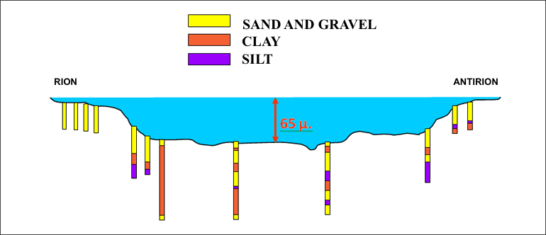
The seabed profile presents steep slopes on each side and a long horizontal plateau about 60 meters below sea level. No bedrock had been encountered during investigations down to a depth of 100 meters below seabed. Based on a geological study, it is believed that the thickness of sediments made of thick layers of clay mixed in some areas with fine sand and silt is greater than 500 meters.
 Earthquakes & Tectonic movements
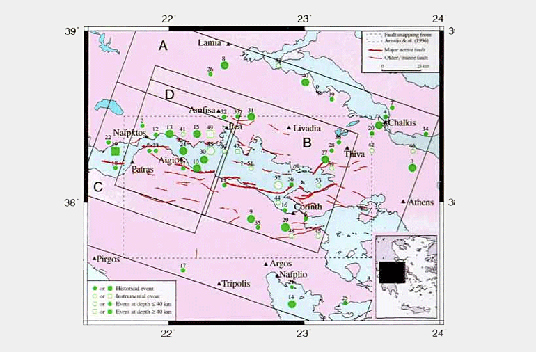
In the Corinthian Gulf and more specifically in the Northern cost of the Peloponnese a large number of active faults are found, i.e. Xilokastro, Aegion, Eliki, Psathopirgos, Patras etc. as shown on the relevant map.
These faults generate the majority of earthquakes that occur in the area as a result of tectonic movements between Central Greece and Peloponnese, which reach several millimeters per year.
The seismic hazard analysis concluded that near-field earthquakes with a magnitude up to 6.5 of the Richter scale are possible. On the map, the circles and square symbols represent historical & instrumented earthquakes with magnitude greater than 5.5R.
Winds
Due to the morphology of the surrounding mountains, the Rion-Antirion strait is known for the frequent and strong winds. The reference wind speed (hourly average, 10 meters high, 120 years return period) was estimated, from a large database of wind measurements, to be 30 m/sec.
Design Loads
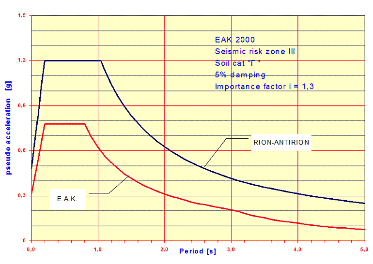
The design seismic loads are presented in the form of a response spectrum at seabed level. The peak ground acceleration is equal to 0.48g and the maximum spectral acceleration is equal to 1.2g for periods between 0.2s and 1.0s. This spectrum is supposed to correspond to a 2,000-year return period, or 5% probability of exceedance for the service life of 120 years. In the following figure the design spectrum of the Bridge is compared with the one required by Greek Seismic Code (EAK 2000).
Taking into account the tectonic movements in the area and the 120 years design life of the bridge, contractual specifications required the bridge to accommodate possible fault movements up to 2m in any direction, horizontally and/or vertically between two adjacent piers, combined with 1/500 vertical tilt of the pylons.
The reference wind speed (10 meters high, 120 years return period) considered was of 32 m/sec. At deck level (57 meter above sea level) the reference wind speed (average 10’) is 50 m/sec. Flexible decks, however, such as cable-stay (i.e. Rion-Antirion Bridge) and suspension bridges are prone to aerodynamic instabilities. Existing standards require that the aerodynamic stability of flexible bridges with span larger than 200 meters to be confirmed with aerodynamic tests. For the Rion-Antirion Bridge, the specifications required that the critical wind speed for flutter instability should be higher than 74 m/sec, and that vortex shedding should remain limited.
In addition, the bridge must be capable to withstand the impact from an 180,000 dwt tanker sailing at 16 knots. This corresponds to an equivalent horizontal static load of 28,000 tons applied at a height of 67m from the pier base (3 meters above normal sea level).
Design Concept
From the beginning it has been clear that the critical load for most of the structure is the accidental seismic load combination. The critical accidental seismic load combination consists of the design earthquake combined with 50% of the tectonic movements.
The choice of the present design was made after examination of a wide range of possible solutions in terms of span type (suspension spans vs. cable-stayed spans) and foundation concepts. Particularly with regard to the foundations, the bearing capacity and the corresponding construction methods were a major concern in these difficult environmental conditions characterized by poor soil conditions, significant seismic accelerations and large depth of water. Alternative foundation concepts (such as pile foundations, deep embedded caissons and soil substitution) were investigated with their relative merits in terms of economy, feasibility and technical soundness. This analysis showed that a shallow foundation was the most satisfactory solution as long as it was feasible to significantly improve the top 20m of soil. This has been achieved by means of metallic inclusions. Although these foundations resemble piled foundations, they do not at all behave as such: no connection exists between the inclusions and the caisson raft, which will allow for the foundation to uplift partially or to slide with respect to the soil during a seismic event.
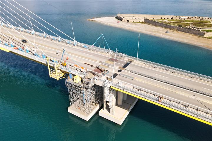
Another unique feature of this project lies in its continuous cable-stayed deck, which, in addition to being the longest in the world, is fully suspended. This creates an effective isolation system significantly reducing seismic forces in the deck and allowing the bridge to accommodate fault movements between adjacent piers thanks to its flexibility. In the transverse direction the deck will behave like a pendulum and its lateral movements must be buffered. This is achieved with the use of 4 hydraulic dampers at the pylon locations and two at the transition piers. They are able to limit the relative lateral displacements between the deck and the pylons and dissipate large amount of energy during a seismic event. However, the deck has to be kept in place during the strongest winds to prevent any unnecessary strain of the dissipation system. For that reason, it is connected to each pylon by a horizontal metallic strut (called fuse restrainer), which will break only during a seismic event of low occurrence, then allowing dampers to step into action.
The expansion joint has been designed to accommodate maximum movements without any damages (in serviceability limit state (SLS) and limited/controlled damages in case of occurrence of the design earthquake.
Bridge Description
 The bridge consists of the following structures:
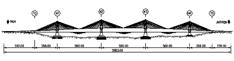
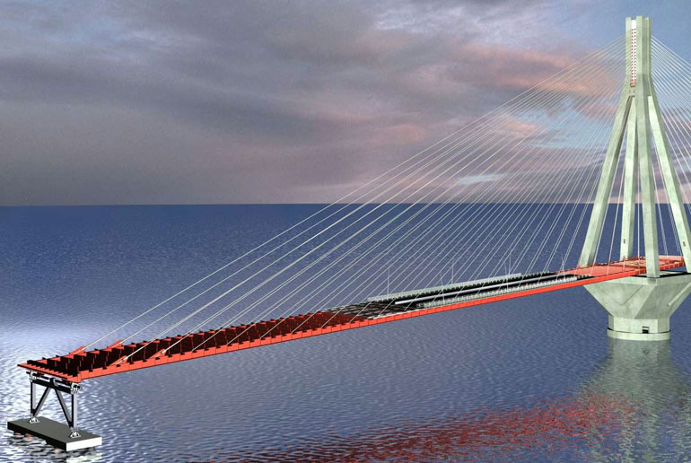
- The main bridge which is a multi-span cable-stayed bridge, 2,252 meter long, with a span distribution equal to 286m-560m-560m-560m-286m.
- Two approach viaducts, with 392 meters on Rion side (composite deck) and 239 meters on Antirion side (prestressed simple supported beams).
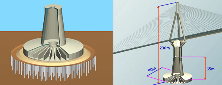 As already mentioned, the upper soil layers, under the pylon foundation, are reinforced with inclusions, which are 2-m diameter hollow steel pipes 25 to 30 meters long driven at a regular spacing of 7 meters. About 110-200 pipes, depending on the case, are driven in at each pier location. A three meter thick, properly levelled, gravel layer tops them. Foundations (consisting of 32 caissons) are 90-meter diameter reinforced concrete caissons (called footing) resting on the gravel layer.
A cone whose diameter ranges from 38 meters to 26 meters forms the lower part of the pier. The upper pier bears an octagon section structure (pier shaft) and a reverse pyramid with a height of about 15 meters (pier head). Each pylon is composed of a 38-meter sided square base (pylon base), and four reinforced concrete legs. The legs, with a section of 4 by 4 meters, are embedded in the 4 corners of the pylon base to form a monolithic structure. They join at the top to the pylon head to give the necessary rigidity to support unsymmetrical service loads and seismic forces.
 The stay cables are in two inclined arrangements, with their lower anchorages on deck sides and their upper anchorages at the pylon top. They are made of 43 to 73 parallel galvanized strands individually protected with an extruded layer of HDPE. Finally, all strands are placed inside a HDPE duct. The cable stay system, which is supplied by Freyssinet (member of Vinci Group), is equipped with special accessories related to its behavior during a major earthquake. It includes wedge-blocking devices in case that the cable is unloaded and bending guiding tubes at the anchorage to control the curvature of the cable during earthquake oscillations.
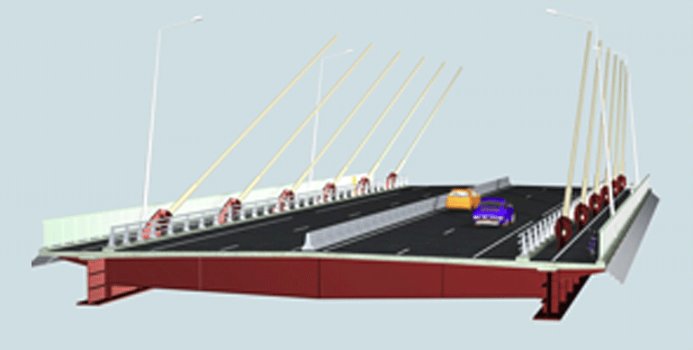
The deck is 27.2 meters wide with two traffic lanes plus an emergency lane and a pedestrian walkway in each direction. It is a composite structure with a steel frame made of two longitudinal 2.2-meter high plate girders on each side and transverse plate girders spaced every 4 meters. The top slab is made of reinforced concrete. Extensive aerodynamic wind tunnel tests were performed by CSTB – Nantes in order to define the best geometry of the deck section and ensure that all aerodynamic requirements are satisfied.
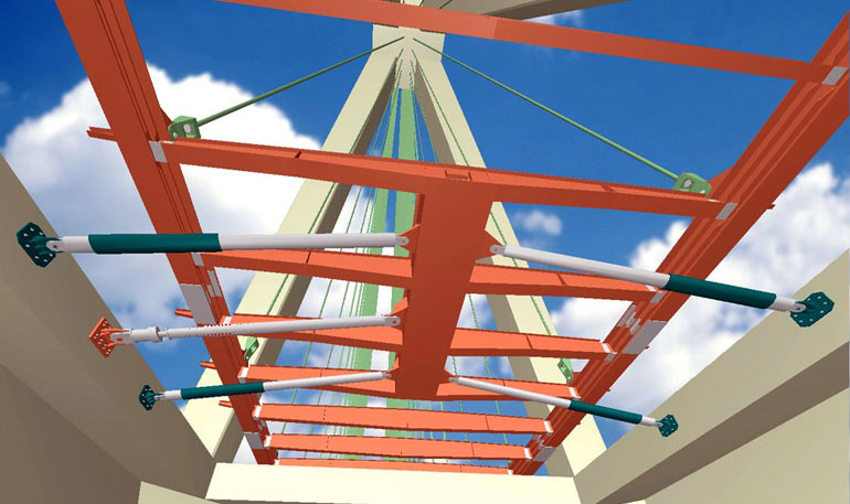 The deck superstructure is continuous and fully suspended by means of stay cables for its total length. An innovative energy dissipation system connects the deck to the top of each pier and limits the lateral movement of the deck during the specified earthquake, while dissipating the seismic energy. The seismic protection system comprises fuse restrainers (10.5 MN and 3.5 MN capacity at main piers and transition piers, respectively) and viscous dampers (3.5 MN capacity each) acting in parallel, connecting in the transverse direction the deck to the piers. The restrainers are designed as a rigid link intended to protect the hydraulic devices by withstanding the wind loads. Under an earthquake, the fuse restrainers are designed to yield, leaving the viscous dampers free to dissipate the energy induced by the earthquake into the structure. The hydraulic dampers, which were manufactured by FIP-Industriale S.p.A are capable of undergoing displacements of -1650mm/+1850mm at the main piers and -2600mm/+2600mm at the transition piers. After the seismic event, parts of the fuse restrainers can be replaced to ensure the stability of the deck within a very small time window.
 In the longitudinal direction, the deck is free to accommodate all thermal and tectonic movements. For this reason the abutments are steel rotating frames (hinged on their ends) to accommodate the large movements of 2,252-m long deck. Between the main bridge and the viaducts, expansion joints, supplied by Maurer Söhne, accommodate a service movement of 1.22m (closing) and 1.26m (opening) in longitudinal direction, and have been designed for a maximum movement of 2.20m (opening) and 2.81m (closing) in longitudinal and +/- 2.50m in lateral direction for the specified earthquake.
Regarding the building materials, most of the bridge elements are reinforced concrete structures. The concrete class varied mainly from C45/55 to C60/75 and the steel grade for the reinforcing bars was S500s. For prestressed structures (on pylon base and pylon head), the strand tensile characteristic strength was fpk=1860MPa. The main deck’s frame, the pylon head’s caisson and the rotating frame (at the abutments) are made of structural steel grade S460 and/or S355. Finally the cable stay strands have a guaranteed ultimate tensile strength FGUTS=1770MPa.
Construction methods
Construction methods and the construction works sequence for the foundations were those commonly used for the construction of offshore concrete platforms:
- construction of the foundation footings in a dry dock up to a height of 15m in order to provide sufficient buoyancy;
- towing and mooring of these footings to a wet dock of sufficient depth;
- construction of the conical part of the foundations at the wet dock in a floating condition secured by chains and easily accessible from land with the use of floating temporary bridges;
- Construction of the sub-soil in-situ foundation with specialized marine equipment;
- towing and immersion of the foundations at final position.
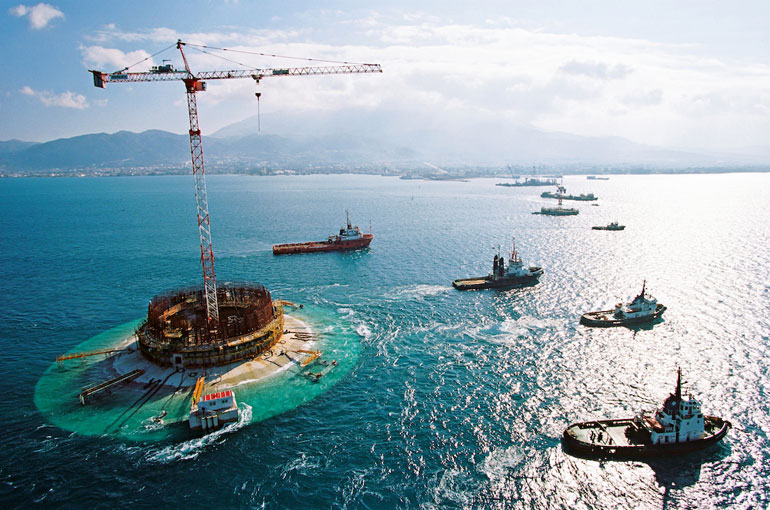
However, some features of this project made the construction process of its foundations quite exceptional.
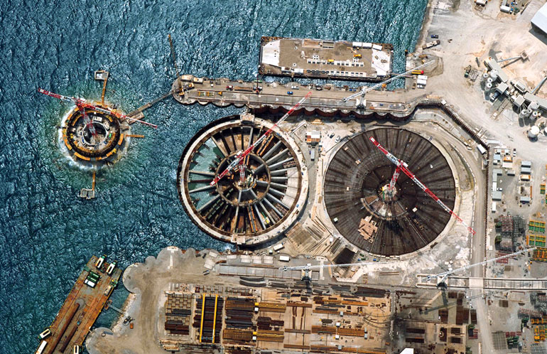 The dry dock was established near the site. It was 200m long, 100m wide, 14m deep, and could accommodate the simultaneous construction of two foundations. It had an unusual closure system: the first foundation was built behind the protection of a dyke, but once towed out, the second foundation, the construction of which had already started, was floated to the front place and used as a dock gate.
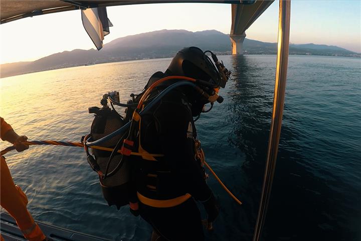
Dredging the seabed, driving inclusions, placing and levelling the gravel layer on the top, with a depth of water reaching 65m, was a major marine operation, which necessitated special equipment and procedures. In fact, a tension-leg barge was custom-made, based on the well-known concept of tension-leg platforms but used for the first time for movable equipment. This concept was based on active vertical anchorage to dead weights lying on the seabed. The tension on these vertical anchoring wire ropes was adjusted in such a way to offer the required stability to the barge vis-à-vis the see movements and the loads managed by the crane that equipped the barge deck. By increasing the tension of the anchoring wire ropes, the barge buoyancy allows the dead weights to lift from the seabed. Then the barge, together with its dead weights may float to a new position.
As already stated, once completed the pier bases were towed then driven at their final position. Compartments created in the footings by the radial beams were used to control trim and sinking by differential ballasting. Then the pier bases were filled with water to accelerate settlements, which are significant (between 0.1 and 0.2m). This pre-loading was maintained during pier shaft and pier head construction, thus allowing a correction for potential differential settlements before erecting pylons and deck superstructure.
The deck of the main bridge was erected using the balanced free-cantilever technique, with 12m long prefabricated deck elements comprising also their concrete slab. The total weight of a prefabricated segment was 340 tons and it was placed with a floating crane (TAKLIFT 7). The rate of erection of completed deck structure was up to 60m per week.